D.A.V.I.D. (Dynamic All Electric Vehicle with Intelligent Devices)
An AI-powered electric go-kart with real-time obstacle detection, built from the ground up. Led a 5-person team through development, then evolved the system into a graduate-level smart vehicle platform featuring depth-camera processing and multi-object tracking.
Project Overview
My Role
Technical Deep Dive
Team & Collaboration
Impact & Lessons
Project Overview
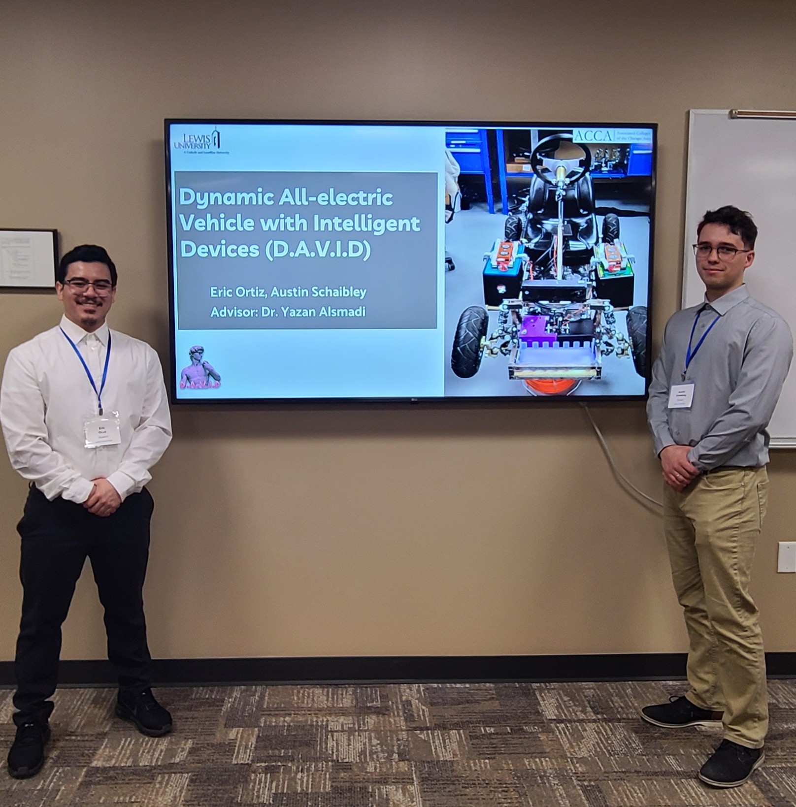
The DAVID project began as a senior capstone, and became the most ambitious hardware-software integration project ever built in our department. Our goal was to build an all-electric, AI-assisted recreational vehicle with object recognition, real-time obstacle avoidance, and emergency braking capabilities. The final product was a fully functioning go-kart (max speed 50MPH) powered by dual 48V battery packs and a 6kW motor, featuring an integrated depth camera system to detect and respond to hazards. Later, I continued development as part of my master's project, redesigning the system to support YOLOv8-based object detection and multi-object tracking with OC-SORT. What started as a safety-first concept became a scalable smart vehicle prototype, capable of seeing, processing, and reacting in real time.
The D.A.V.I.D. Project
D.A.V.I.D. Team Logo
My Role
As Project Manager, I wore many hats. I led a five-person interdisciplinary team, coordinated timelines, managed deliverables, and maintained alignment through weekly meetings and Gantt chart updates. I wrote extensive technical documentation, including stakeholder analyses, system requirements, and testing/verification plans. I also heavily supported hardware integration by designing and soldering PCBs, assembling electronics, installing DC/DC converters, and designing/3d printing custom Fusion 360 parts. On the software side, I co-developed the object detection pipeline and later transitioned to become the lead software architect during our master’s extension. I handled integration of YOLOv8 and OC-SORT in a multi camera (depth data and RGB) system, enabling the vehicle to detect, track, and brake in response to real-world objects.
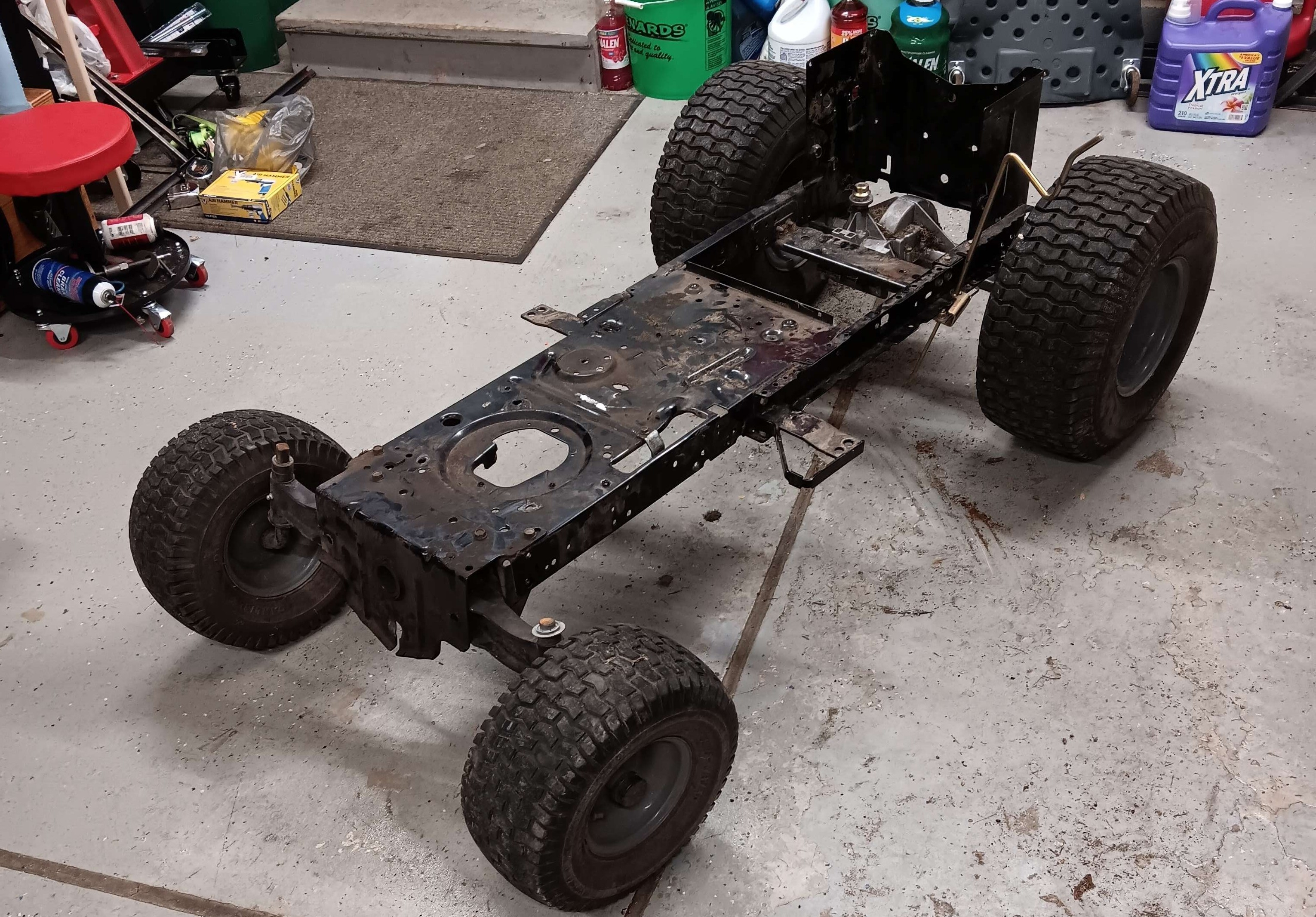
Before Project production
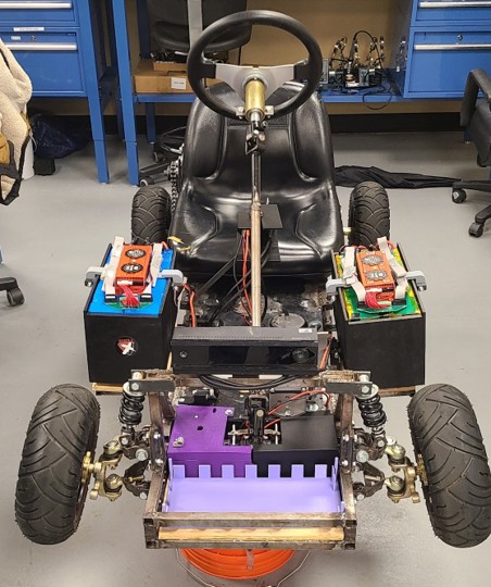
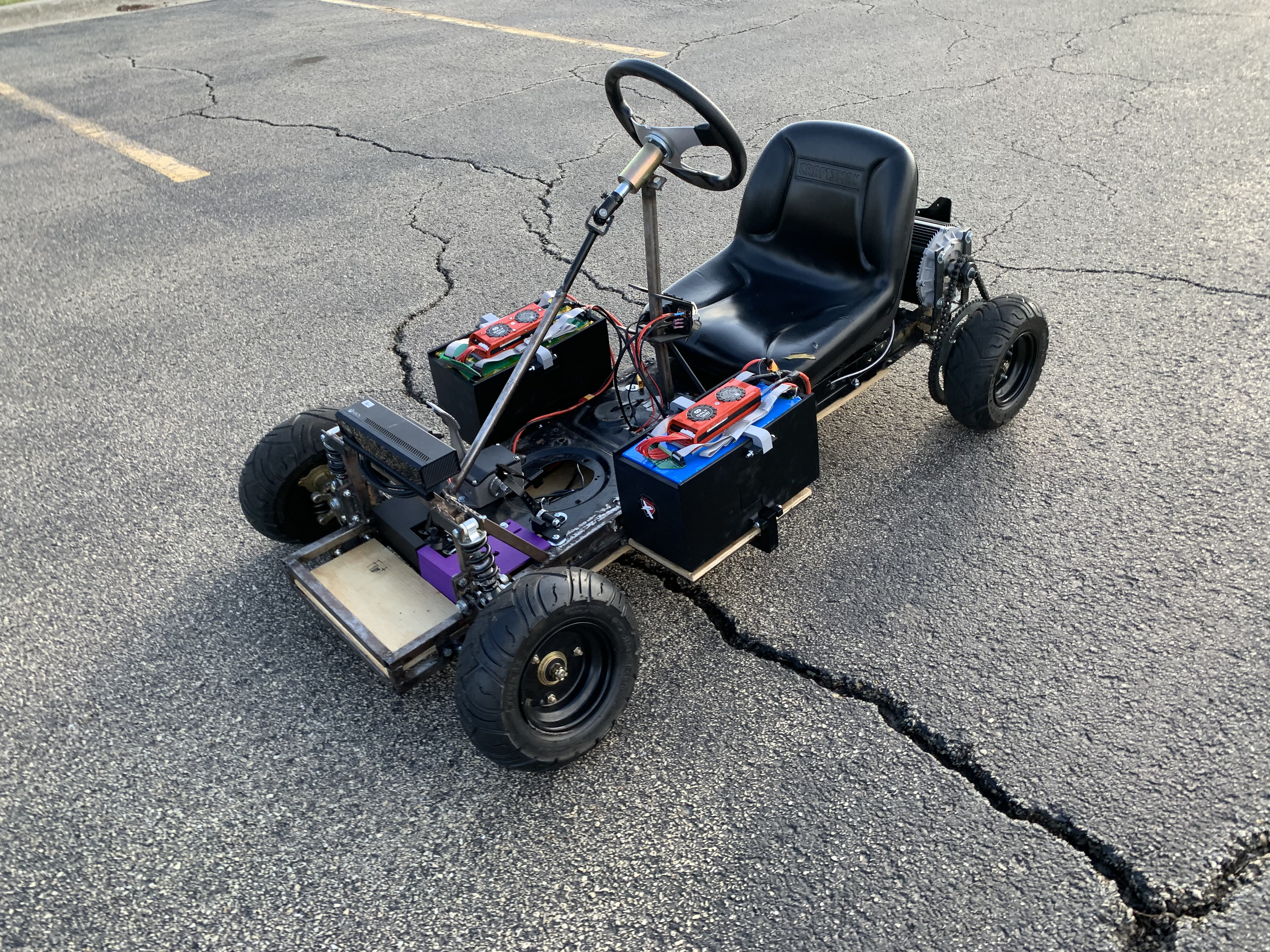
After Project Production
Technical Deep Dive
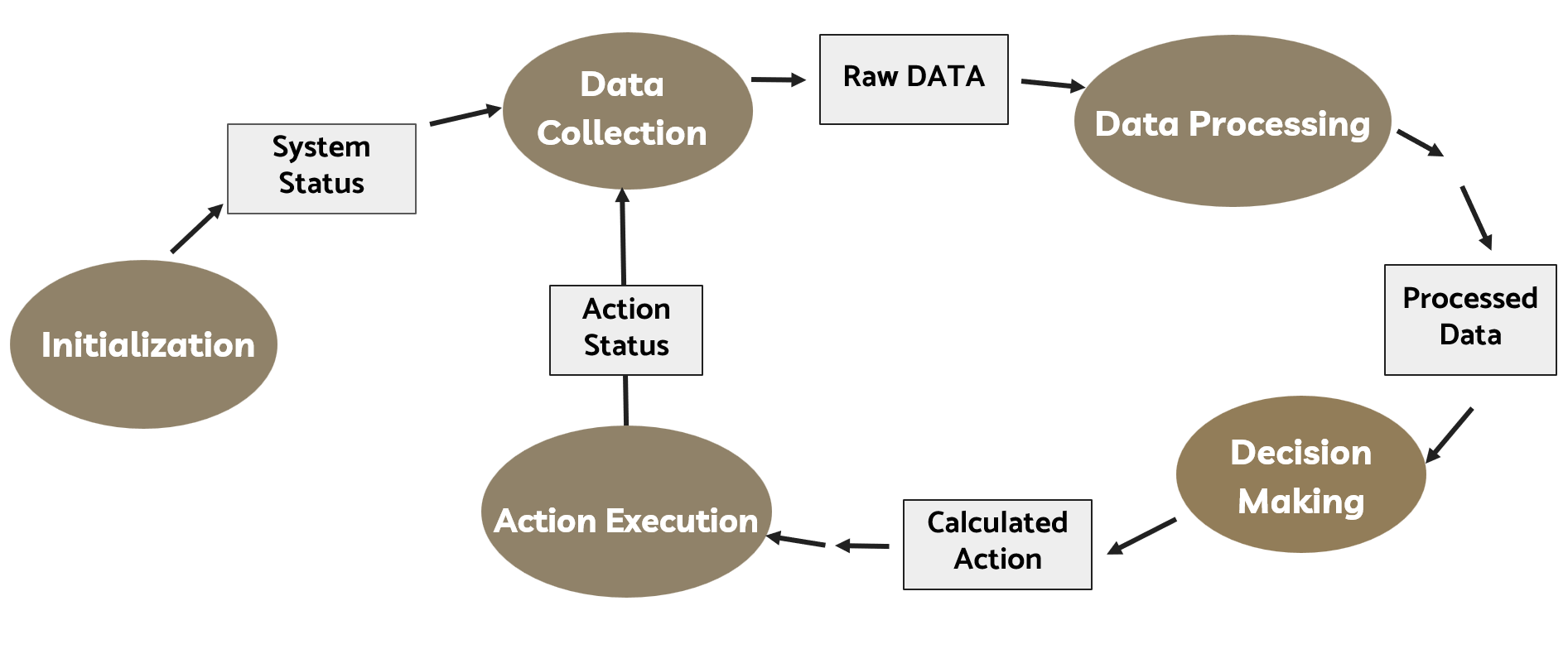
The core safety system uses a Microsoft Kinect V2 depth camera to capture RGB and depth data at 30 FPS. In the original version, this data was analyzed in real time to detect obstacles and initiate automatic braking via a relay-controlled motor controller. In the master’s version, we implemented YOLOv8 for object classification and OC-SORT for multi-object tracking. Object detection was constrained to an 8-meter range to meet real-time latency and braking requirements. The system architecture includes a Windows-based main processor, an Arduino microcontroller for relay activation, and a braking pin signal routed through a solenoid relay. We also performed verification tests for camera latency, braking response time (<500ms), and component reliability. Top speed reached 50mph; automated braking succeeded in testing up to 15mph with a stopping distance of 12–13 meters.
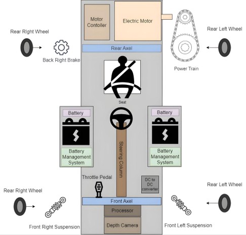
Component Implementation Design
Onboard Depth Camera Tracking
Onboard AI Camera Tracking
Software State Model Design
Team & Collaboration
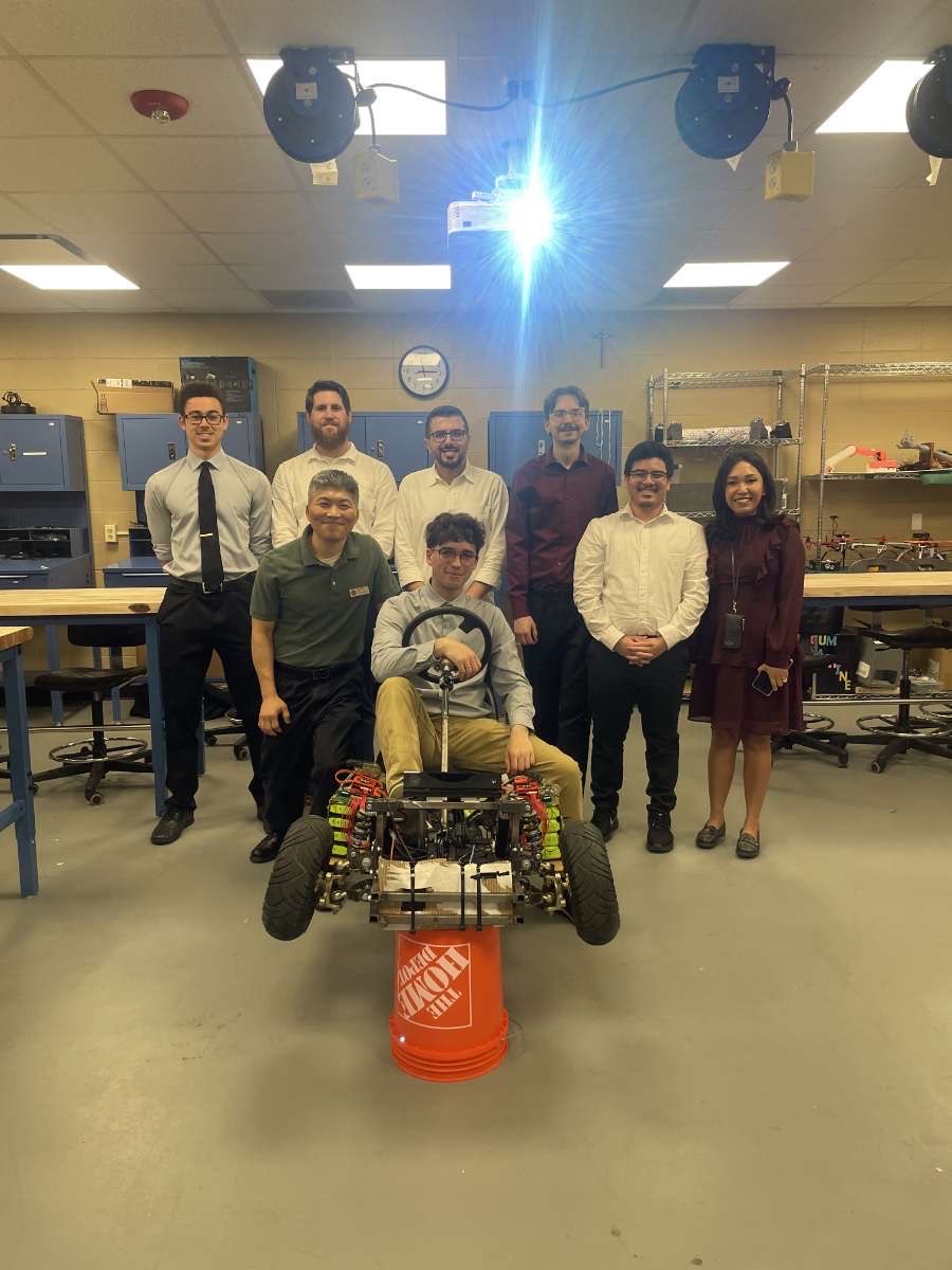
Our team of five included specialists in mechanical, electrical, software, and simulation disciplines. I assigned roles based on strengths: lead software, simulations/electronics, mechanical, and electrical systems. I maintained the full team schedule and communication flow, acting as the liaison between technical areas. My co-lead and I continued the project post-graduation as a two-person master’s group, with me focusing on AI software architecture and him handling system upgrades and physical reinforcement. We worked in lockstep to debug hardware/software issues and iterate on designs quickly.
Masters presentation for the Associated Colleges of the Chicago Area (ACCA)
Capstone Team and Professors
Impact & Lessons
This project pushed me to the limits of leadership and technical ability and helped me grow into an engineer who can guide projects from idea to impact. I learned how to communicate complex requirements, lead a multidisciplinary team, and build systems that have to work in the real world. The master's continuation taught me to dive deeper into AI and own a full pipeline from theory to implementation. I'm incredibly proud of what we achieved, especially because we turned an undergrad idea into a working smart vehicle platform. The project now is being used by university students for further enhancements and research studies.
Autonomous Drone Integration Collaboration
A crossdisciplinarity volunteer project exploring whether autonomous drone programming could fit into Lewis University’s Computer Science curriculum. Built and simulated autonomous missions using DroneKit in Python on a custom quadcopter platform.
Project Overview
My Role
Challenges & Findings
Technical Deep Dive
What I Learned
Project Overview
This project was a collaborative initiative between students in Electrical & Computer Engineering (ECE), Computer Science (CS), and the drone operations program. Our mission: explore whether hands-on autonomous drone programming could be integrated into the CS department's Object-Oriented Programming (OOP) course. As volunteer students, we sourced a drone kit, built the platform from scratch, and programmed autonomous flight behaviors using Python and the DroneKit SDK. We successfully simulated flight missions including takeoff, waypoint travel, and return-to-launch (RTL), and presented our findings to faculty. While ultimately determined unfeasible as a CS-only curriculum module, the project revealed key gaps in embedded systems knowledge and showcased the potential for interdisciplinary technical learning.
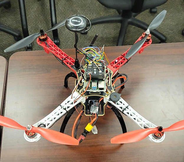
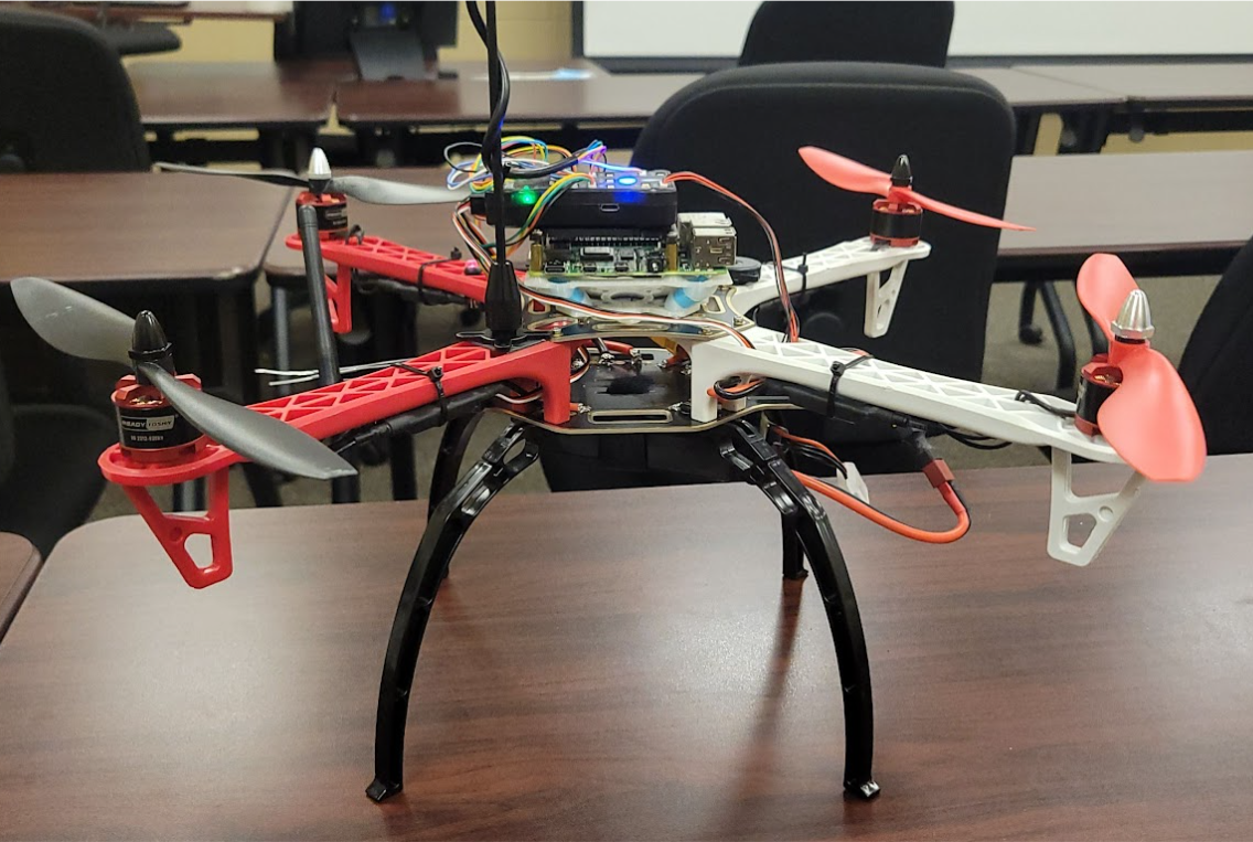
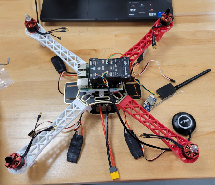
Overhead View of Completed Drone
Side View of Completed Drone
My Role
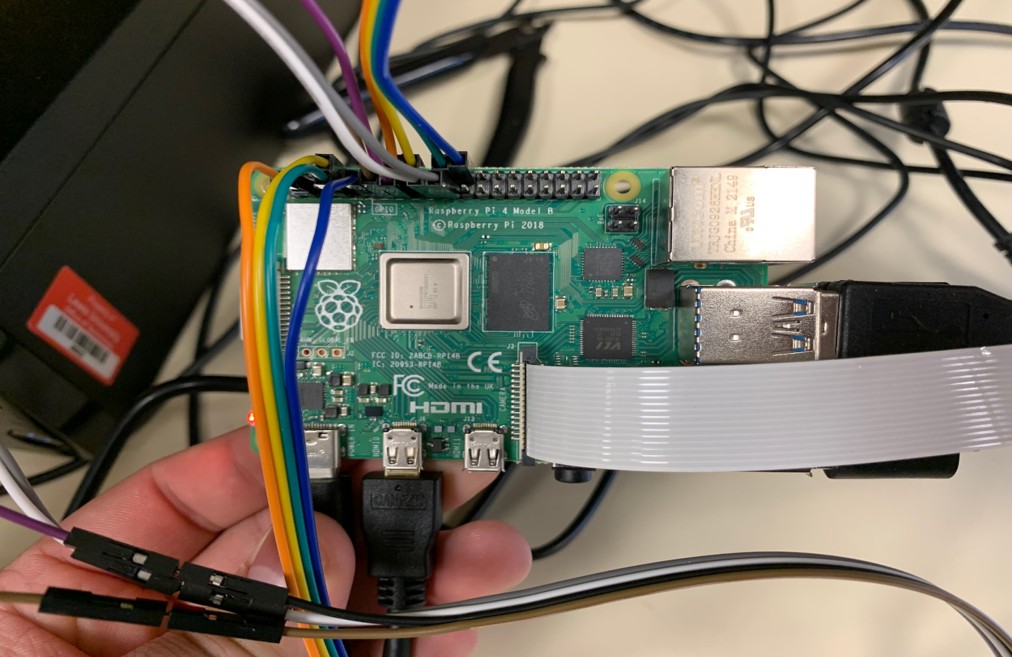
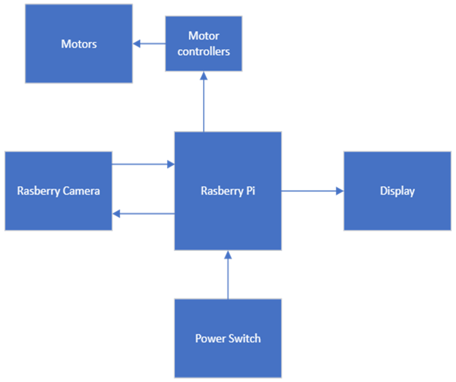
As one of only two Electrical and Computer Engineering students in the group, I led most of the hands-on development work. I assembled and wired the drone platform, integrating a Pixhawk flight controller with a Raspberry Pi, GPS, telemetry, and 4 motor controllers. I also co-developed the Python code that powered our simulated autonomous flights, using DroneKit to script core behaviors like takeoff, navigation, and RTL. Beyond technical execution, I served as a bridge between the CS students and the hardware side, helping the group understand the limitations, requirements, and debugging involved in working with embedded robotics.
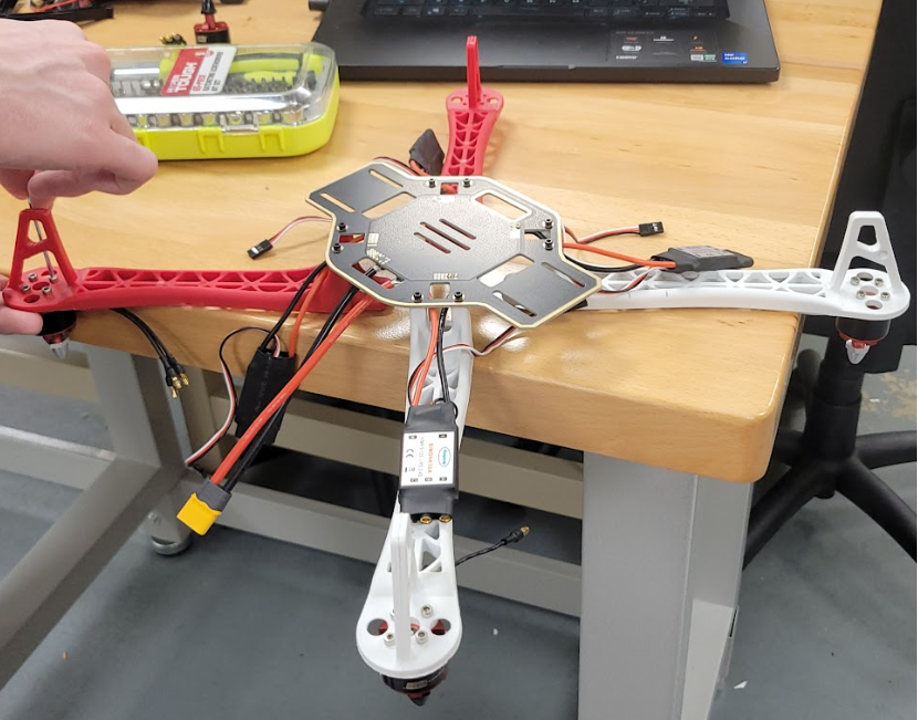
Drone Assembly
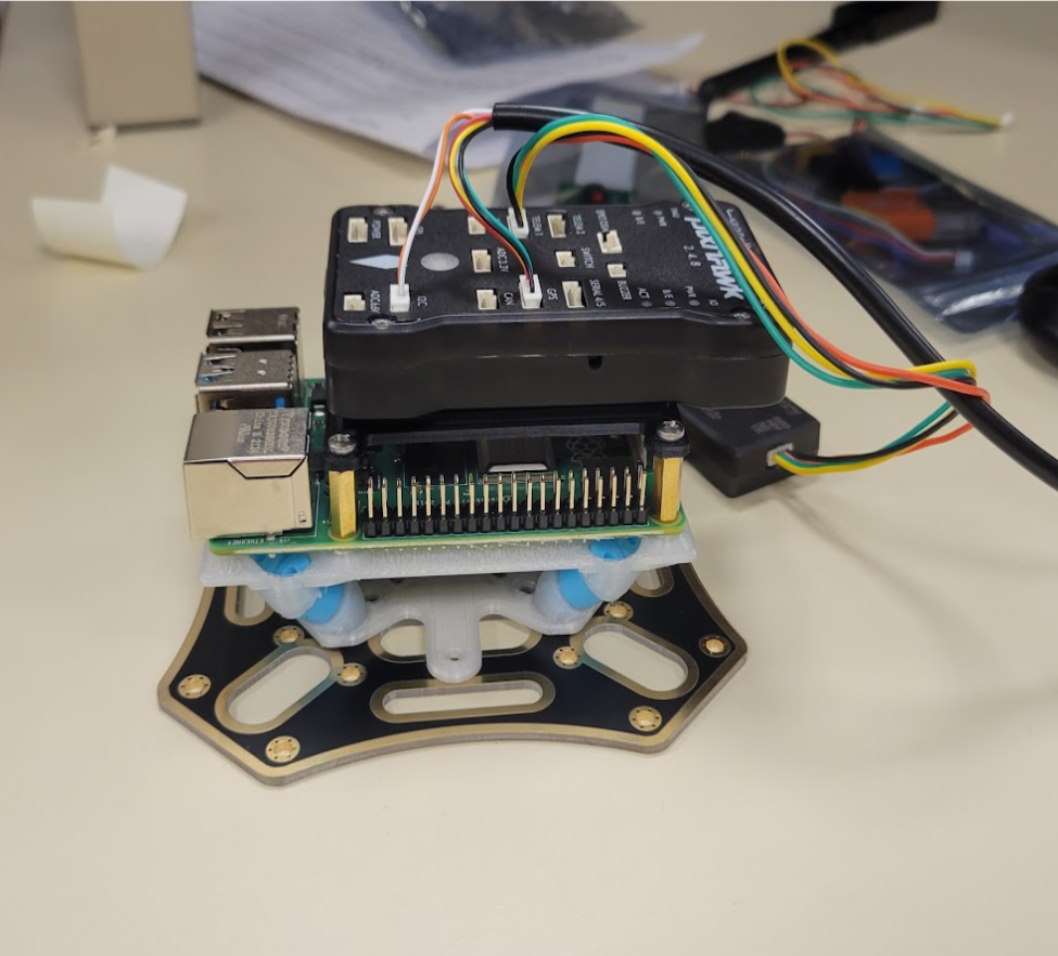
Onboard Controller Setup
Challenges & Findings
One of the key challenges we faced was the difference in background knowledge across the team. While the CS students brought strong software skills, some hadn’t worked with embedded hardware before, which made aspects like wiring, power systems, and sensor integration more complex to navigate as a group. As the only ECE students, my teammate and I naturally took on the hardware-heavy tasks while sharing what we could with the team. This highlighted a larger issue: while the idea of merging autonomous drone programming into a CS OOP course was exciting, it relied on knowledge outside the course's typical scope. In the end, the project worked well as a proof of concept, but it showed that broader integration into the curriculum would require more foundational hardware exposure.
Functionality testing
Technical Deep Dive
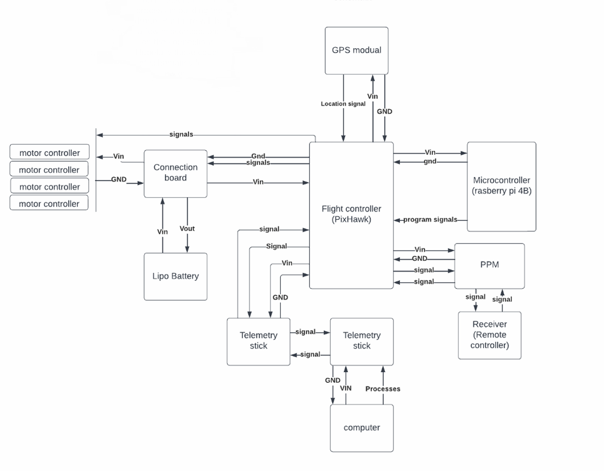
The project utilized a Drone Dojo quadcopter kit as the base platform, equipped with a Pixhawk flight controller integrated with GPS and telemetry modules for real-time positioning and communication. The computational layer was provided by a Raspberry Pi, acting as the onboard processor for autonomous commands. Power was supplied by an 11.1V 3S 3000mAh LiPo battery, delivering consistent output to the motors and sensors. On the software side, we programmed in Python 2.7, leveraging the DroneKit SDK to script flight logic for autonomous takeoff, navigation, and return-to-launch behaviors. Mission Planner was used for calibration, parameter tuning, and manual control testing. Additionally, we used SITL (Software-In-The-Loop) simulation to validate flight behavior in a virtual environment before testing on hardware.
Component Implementation Design
Disassembled Drone
What I Learned
This project gave me early hands-on experience working across disciplines and communicating with teammates from different technical backgrounds. I learned how to troubleshoot hardware without much documentation, adapt code for new hardware systems, and navigate the gaps between software-focused and hardware-focused thinking. It also taught me how to evaluate feasibility, present limitations clearly, and contribute to a project that was as much about exploration as it was about execution.
A Raspberry Pi–powered system designed to automatically sort resistors using computer vision and OpenCV. Built for fun, functionality, and frustration-reduction as lab assistants, the project gained traction and placed 2nd at the IEEE EIT 2023 Poster Competition.
Project Overview
My Role
Technical Deep Dive
Results & Challenges
Project Overview
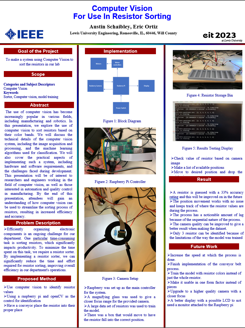
The Resistor Sorter was a creative hardware/software final project built for our Hardware-Software Integration course. The idea stemmed from our experience as lab assistants, where we often had to manually sort resistors after lab sessions. Using a Raspberry Pi, OpenCV, and stepper motors, we designed a system that could classify resistors based on their color bands and sort them into labeled bins automatically. Though we never fully finished it, the project caught a lot of attention and placed 2nd in the 2023 IEEE EIT poster competition hosted at Lewis University.
IEEE EIT 2023 Project Poster
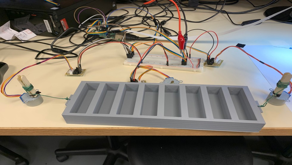
Sorting System
My Role
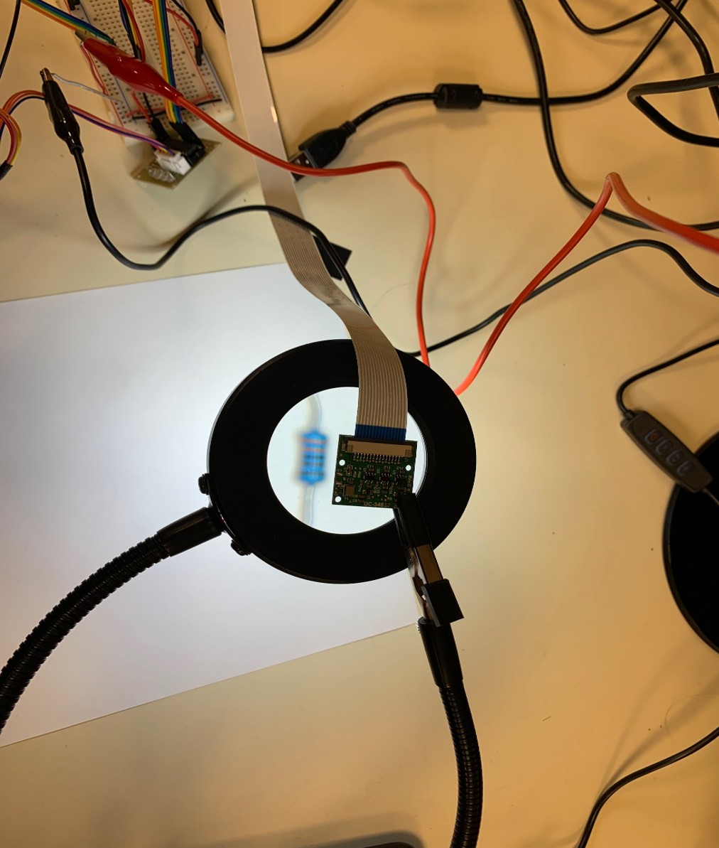
I co-led a two-person development team and worked on both the hardware and software sides of the system. On the hardware end, I wired and integrated a Raspberry Pi 4 with a conveyor belt system, a Pi camera module, and stepper motors to control bin positioning. I also handled image preprocessing and camera tuning, using a magnifier lens to improve focus and resolution. On the software side, I contributed to developing a basic image classification pipeline in OpenCV, testing color band recognition and setting up logic for controlling movement and bin placement based on predicted resistance values.
Main Controller unit
Technical Deep Dive
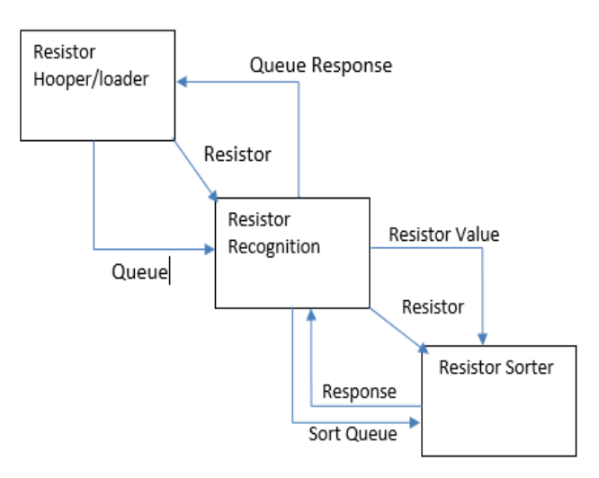
The system followed a three-step process:
Image Acquisition: A resistor was placed on a conveyor belt and passed beneath a Raspberry Pi Camera for scanning,
Classification: The image was processed using OpenCV to detect and interpret the resistor’s color bands in order to estimate its resistance value,
Sorting: Once classified, a stepper motor rotated the appropriate bin into place, and the resistor was released into it.
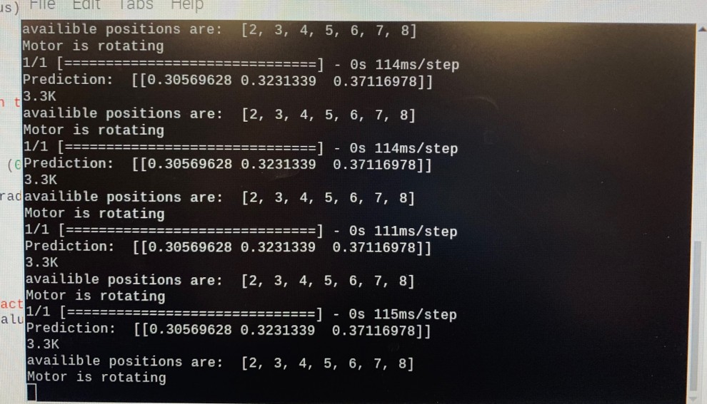
The Raspberry Pi managed both the image analysis and physical control logic. A simple graphical display was used to show the predicted value for each resistor in real time.
Hardware Integration Overview
Resistor Sorting Process Flow
Results & Challenges
The sorting system functioned reliably, but the recognition algorithm achieved only about 33% accuracy. We later realized this was due to training the model on full resistor images instead of isolating color bands, leading to poor generalization. Camera limitations (resolution, focal range) also affected image clarity. Despite the low accuracy, the end-to-end system (input → prediction → physical sorting) worked and proved the concept. With more time and better imaging tools, we saw clear potential for improved results.